DANFOSS FC-304/302/301 VFD DRIVE PARAMETER SETTINGS PART-2
 |
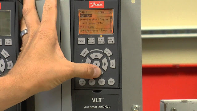
| 60 Hp Danfoss FC-301 Drive |

| DANFOSS FC-304 VFD DRIVE PARAMETER LIST | ||
| Parameter | Setting | Description |
| 0-02 | 1 | Motor Speed Unit (Hz) |
| 1-20 | 22 kw | Motor Kilowatt |
| 1-21 | 18 HP | Motor HP |
| 1-22 | 415 Volt | Motor Voltage |
| 1-23 | 50 Hz | Motor Frequency |
| 1-24 | 23 Amps | Motor Current |
| 1-25 | 1450 Rpm | Motor Speed |
| 3-00 | 0 | Min - Max |
| 3-01 | 3 | HZ |
| 3-02 | 0 Hz | Min Reference |
| 3-03 | 50 Hz | Max Reference |
| 3-04 | [0] Sum | Reference Function |
| 3-10 | [0] 0.00 % | Preset Reference |
| 3-11 | 5.0 Hz | Jog Speed [Hz] |
| 3-12 | 0.00 % | Catch up/slow Down Value |
| 3-13 | 0 | Linked to Hand / Auto |
| 3-14 | 0.00 % | Preset Relative Reference |
| 3-15 | 1 | Reference Resource 1 (Analog Input 53) |
| 3-16 | 20 | Reference Resource 2 (Digital pot meter) |
| 3-17 | 11 | Reference Resource 3 (Local Bus Reference) |
| 3-18 | [0] No function | Relative scaling Reference Resource |
| 3-41 | 30 s | Ramp Up |
| 3-42 | 30 s | Ramp Down |
| 4-12 | 0.0 Hz | Motor speed limit low |
| 4-14 | 50 Hz | Motor speed limit High |
| 5-00 | [0] PNP | Digital I/O mode |
| 5-01 | [0] Input | Terminal 27 mode |
| 5-10 | [8] Start | Terminal 18 Digital Input |
| 5-11 | [10] Reversing | Terminal 19 Digital Input |
| 5-12 | [2] Cost Inverse | Terminal 27 Digital Input |
| 5-14 | [1] Reset | Terminal 32 Digital Input (External PB) |
| 5-15 | [0] No function | Terminal 33 Digital Input |
| 5-40 | 10 (Alarm) | Function Relay |
| 5-41 | 0.01 S | ON Delay Relay |
| 5-42 | 0.01 S | OFF Delay Relay |
| 6-10 | 0.0 v | Terminal 53 Low Voltage |
| 6-11 | 10.0 v | Terminal 53 High Voltage |
| 6-14 | 30 Hz | Terminal 53 low ref / feed back |
| 6-15 | 40 Hz | Terminal 53 High ref / feed back |
| 8-50 | 2 (logic AND) | Costing |
| 8-51 | 3 (Logic OR) | Quick stop |
| 8-52 | 3 (Logic OR) | DC Brake |
| 8-53 | 3 (Logic OR) | Start |
| 8-54 | 3 (Logic OR) | Reversing |
| 8-55 | 3 (Logic OR) | Set up select |
| 8-56 | 3 (Logic OR) | Presence Ref Select |
| 16-62 | 10.0 | Analog Input (Actual reference Volt) |
| | | |
| This Parameter Setting is Suitable for Manual ON/OFF Mode and Pot meter mode. | ||
DANFOSS 301 TERMINAL CONNECTION :
 |
| Drive Port |
Wire Port :
Wire Connection :
- Take out ( +24v OUTPUT ) from 12 th Terminal Port and give to 18 th ( DIGITAL INPUT) Terminal port also loop 12 and 27 Terminal port , for the Purpose of ON / OFF the VFD drive with External START,STOP Push Button.
- Take out ( +24v OUTPUT ) from 13 th Terminal Port and give to 32 ( DIGITAL INPUT) Terminal port , for the Purpose of RESET the Alarm with External Push Button.
- Take out ( +10v dc OUTPUT ) from 50 th Terminal Port and give to POTMETER 1st terminal and Take out ( COM ANALOG INPUT ) from 55 th Terminal Port and give to POTMETER 3rd terminal , finally Take Regulated Voltage from POTMETER 2nd terminal and give to Drive 53 ( ANALOG INPUT ) Terminal Port.

Factory Reset


No comments:
Post a Comment